

Load Cell Problem? Do These 3 Things First
When a load cell starts giving unstable readings, inaccurate weight values, zero drift, no output, or sudden overload errors, it can quickly interrupt production, quality control, batching, packaging, inventory weighing, or safety monitoring. The first reaction is often to assume the load cell is damaged, but many load cell issues come from installation conditions, wiring problems, moisture intrusion, poor grounding, mechanical interference, or incorrect calibration. Before replacing the sensor, it is better to follow a structured troubleshooting process.
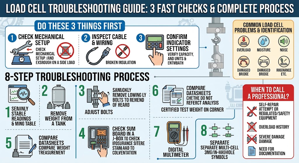
Do these 3 things first:
- Check the mechanical setup first: Make sure the load cell is not overloaded, blocked, twisted, side-loaded, or touching nearby structures.
- Inspect the cable and wiring: Look for loose terminals, damaged insulation, moisture, wrong excitation wiring, shielding issues, or broken conductors.
- Confirm the indicator or transmitter settings: Verify calibration, capacity, decimal point, units, zero range, excitation voltage, and signal input configuration.
These three checks solve a large share of practical load cell problems because a load cell is only one part of a complete weighing system. The sensor may be healthy, but the system can still fail if the mounting base is not rigid, the junction box has moisture, the indicator is misconfigured, or the cable shield is not grounded properly. A good troubleshooting method should separate mechanical, electrical, environmental, and calibration causes before deciding whether the load cell needs repair or replacement.
The following guide is written for engineers, maintenance teams, machine builders, plant operators, and technical buyers who need a practical way to diagnose a load cell issue. It does not guarantee that every load cell can be repaired on-site, but it gives you a clear process to narrow down the problem and decide the safest next step.
Common Load Cell Problems and How to Identify Them
A load cell converts force into an electrical signal, so problems can appear either as a weighing error or as an electrical fault. The key is to match the symptom with the most likely cause. For example, a reading that changes when someone walks near the scale may point to vibration or unstable mounting, while a reading that slowly drifts after washdown may suggest moisture intrusion or insulation resistance problems.
| Cause | How to Identify It | Recommended Action |
|---|---|---|
| Mechanical overload | Reading is permanently shifted, zero cannot return, or output remains abnormal after unloading. | Remove load, inspect mounting, check zero balance, and consider replacement if the sensor is deformed. |
| Side load or binding | Weight changes when the platform is pushed sideways, or readings differ by load position. | Correct alignment, remove mechanical contact, and confirm the load is applied in the intended direction. |
| Loose cable or terminal | Reading jumps, signal drops out, or output changes when the cable is moved. | Tighten terminals, inspect connectors, replace damaged cables, and secure cable strain relief. |
| Moisture intrusion | Drifting readings after cleaning, rain, high humidity, or washdown. | Dry the junction box, inspect sealing, test insulation resistance, and replace compromised components. |
| Incorrect calibration | System is stable but consistently displays the wrong weight. | Verify capacity, units, decimal point, span calibration, and test weight accuracy. |
| Electrical noise | Readings fluctuate when motors, VFDs, relays, or nearby equipment operate. | Improve grounding, separate signal cables from power cables, and check shielding. |
| Damaged load cell bridge | Resistance values are abnormal, signal output is missing, or zero balance is far outside normal range. | Perform electrical measurements and replace the load cell if bridge damage is confirmed. |
| Indicator or transmitter fault | Multiple sensors show the same fault, or a known good load cell still reads incorrectly. | Check excitation output, input range, configuration, firmware settings, and terminal connections. |
This table is useful because replacing a load cell without checking the surrounding system can waste time and money. A new sensor installed into the same misaligned bracket, wet junction box, or noisy cable route may fail again or show the same unstable behavior. Always diagnose the system as a whole.
Step-by-Step Load Cell Troubleshooting Process
A load cell troubleshooting process should move from simple visual checks to deeper electrical testing. This helps avoid unnecessary disassembly and reduces the risk of damaging the sensor, cable, junction box, or indicator. The steps below apply to many strain gauge load cell systems, including platform scales, tank weighing systems, hopper scales, checkweighers, batching machines, force test rigs, and industrial weighing equipment.
Step 1: Confirm the exact symptom before adjusting anything
Before touching calibration settings or wiring, write down what the system is doing. Is the display showing no weight, unstable weight, negative weight, overload, underload, drifting zero, wrong span, or different readings at different positions? Also note when the problem occurs. A load cell that becomes unstable only after washdown has a different likely cause than a load cell that reads incorrectly immediately after installation.
This step matters because vague descriptions such as “the load cell is bad” often lead to poor decisions. A clear symptom helps you separate mechanical problems from electrical problems. For example, a repeatable but incorrect reading usually points to calibration or span settings, while random spikes may point to loose wiring, electrical noise, or damaged cable shielding.
Step 2: Remove the load and check zero behavior
Unload the scale, platform, tank, or fixture as much as safely possible. Observe whether the reading returns to zero or remains offset. If the reading returns to zero slowly, the system may have mechanical friction, structural binding, thermal effects, or moisture-related drift. If the reading remains far from zero after the load is removed, the load cell may be overloaded, mechanically deformed, or electrically damaged.
Do not immediately force a zero reset to hide the problem. Zeroing the indicator may temporarily make the display look normal, but it does not fix a damaged load cell or a mechanical installation issue. If the system must be used for measurement, quality control, or commercial weighing, incorrect zeroing can cause serious measurement errors.
Step 3: Inspect the mechanical installation
A load cell must receive force in the direction and manner it was designed for. Check whether the load cell is mounted flat, whether bolts are tightened correctly, whether the mounting surface is rigid, and whether any part of the structure is touching the platform or vessel. Look for bent brackets, uneven feet, blocked movement, welding distortion, or foreign objects trapped under the scale.
Side loading is one of the most common practical causes of bad readings. If the load cell is designed for vertical compression but the installation applies horizontal force, twisting, or bending, the output may become nonlinear or inconsistent. In multi-load-cell systems, uneven load distribution can also make one sensor carry more force than expected, increasing overload risk.
Step 4: Check the cable, connector, and junction box
Inspect the entire cable route from the load cell to the indicator, transmitter, PLC module, or junction box. Look for crushed cable, cuts, sharp bends, pulled strain relief, loose connectors, corroded terminals, liquid inside junction boxes, or cable runs next to power lines. A damaged cable can cause intermittent faults that look like sensor failure.
For systems with multiple load cells, open the junction box and check whether each sensor is properly connected. Moisture, corrosion, or a loose summing board terminal can create unstable readings across the whole scale. Make sure the shield and ground arrangement follows the equipment design. Poor shielding may allow motor noise, relay switching, or VFD interference to enter the low-level millivolt signal.
Step 5: Verify indicator, transmitter, or PLC input settings
A load cell output is small, so the receiving electronics must be configured correctly. Check excitation voltage, input sensitivity, capacity, decimal place, engineering units, filtering, zero tracking, tare settings, and calibration data. If the load cell was replaced recently, confirm that the new sensor has the same rated capacity, sensitivity, wiring color code, and output type as the previous one.
Do not assume wire colors are universal. Different manufacturers may use different color codes for excitation, signal, sense, and shield conductors. If the wiring is wrong, the system may show negative weight, unstable values, no output, or overload. Always check the datasheet or wiring label before changing connections.
Step 6: Test with a known load or calibrated test weight
Once the system appears mechanically and electrically stable, apply a known load. Use a certified test weight when accuracy matters. Place the load at the center and, for platform systems, also test corners or different load positions. If readings change significantly depending on position, the issue may be leveling, load distribution, mechanical binding, or one faulty load cell in a multi-cell system.
If the system is repeatable but off by a consistent amount, recalibration may solve the problem. If the readings are not repeatable, calibration alone will not fix it. A non-repeatable system needs mechanical, electrical, or environmental correction before calibration is meaningful.
Step 7: Measure electrical resistance when safe and appropriate
If you have the proper tools and training, disconnect the load cell from the indicator and measure input resistance, output resistance, and insulation resistance according to the manufacturer’s specification. Abnormal bridge resistance may indicate internal strain gauge damage, broken wires, or short circuits. Low insulation resistance may indicate moisture ingress, cable damage, or contamination.
Electrical testing should be done carefully because incorrect meter use, wrong terminals, or energized circuits can damage equipment. When the load cell is part of safety equipment, production-critical machinery, or legal-for-trade weighing, electrical diagnosis should be performed by qualified personnel.
Step 8: Isolate each load cell in a multi-cell system
In tank, hopper, floor scale, truck scale, and platform systems, multiple load cells may be summed together. One bad load cell can disturb the whole system. If safe and permitted by the equipment design, isolate each sensor and test output individually. Compare zero output, response to load, and resistance values between sensors of the same type and capacity.
A single sensor with very different behavior from the others is a strong clue. However, do not ignore the mechanical structure. A corner that reads incorrectly may be caused by a bad load cell, but it may also be caused by a warped frame, unstable mounting plate, damaged foot, or load path obstruction.
When Should You Call a Professional?
Some load cell problems can be checked by maintenance staff, but certain warning signs require professional service. This is especially true when the load cell is used in industrial automation, lifting-related force monitoring, batching, safety systems, legal metrology, or expensive production equipment.
- The load cell was overloaded, impacted, dropped, bent, or exposed to unusual force.
- Zero does not return after unloading, even after mechanical interference is removed.
- Resistance readings are outside the manufacturer’s stated range.
- There is moisture, corrosion, chemical exposure, or visible cable damage.
- The system is used for commercial weighing, safety monitoring, or regulated measurement.
- The reading is unstable even after checking wiring, shielding, grounding, and installation.
- Multiple components may be involved, including the load cell, indicator, junction box, PLC module, or transmitter.
- The equipment must be certified, calibrated, documented, or validated after repair.
Professional technicians can use calibrated test equipment, insulation testers, signal simulators, certified weights, and manufacturer documentation to determine whether the problem is in the sensor or the surrounding system. They can also confirm whether the final weighing system meets accuracy and safety requirements after repair.
Load Cell Maintenance and Installation Tips
Preventing load cell problems is usually easier than troubleshooting them after failure. The most important principle is to protect both the mechanical load path and the low-level electrical signal. A load cell can be accurate and reliable for a long time when it is mounted correctly, protected from overload, sealed from moisture, and connected with clean wiring practices.
- Use the correct capacity: Select a load cell with enough rated capacity and overload protection for the application.
- Avoid side load: Use proper mounting kits, alignment hardware, anti-lift devices, or check rods when needed.
- Protect the cable: Avoid sharp edges, crushing, pulling, high-temperature areas, and routes near high-power wiring.
- Control moisture: Use appropriate sealing, cable glands, junction boxes, and environmental protection for washdown or outdoor installations.
- Maintain grounding and shielding: Keep signal wiring clean and separated from motors, VFDs, contactors, and power cables.
- Calibrate periodically: Schedule calibration based on usage, accuracy requirements, environmental stress, and production risk.
- Document changes: Record replacement dates, calibration values, wiring changes, overload events, and repair history.
- Train operators: Prevent shock loading, forklift impact, overfilling, platform abuse, and improper cleaning methods.
A reliable load cell system depends on more than the load cell itself. The structure must transfer force correctly, the electronics must measure the signal accurately, and the environment must not damage the sensor or wiring. When the system is designed and maintained as a complete measurement chain, troubleshooting becomes faster and unexpected downtime is reduced.
Load Cell FAQ
Q1: What is a load cell?
A load cell is a sensor that converts force, weight, or load into an electrical signal. It is commonly used in scales, tanks, hoppers, batching systems, testing machines, and industrial weighing equipment.
Q2: Why is my load cell reading unstable?
Unstable readings may come from vibration, loose wiring, poor grounding, electrical noise, moisture, mechanical binding, side load, or a damaged cable. Start with mechanical and wiring checks before changing calibration.
Q3: Why does my load cell not return to zero?
A load cell may not return to zero because of overload, mechanical deformation, friction, binding, temperature effects, moisture intrusion, or internal bridge damage. Do not simply zero the indicator until the cause is checked.
Q4: Can a load cell be repaired?
In many cases, a damaged load cell is replaced rather than repaired, especially if the internal strain gauge bridge is damaged. External issues such as wiring, connectors, mounting, or junction boxes may be repairable.
Q5: How do I know if a load cell is overloaded?
Signs of overload include permanent zero shift, poor repeatability, abnormal resistance values, visible deformation, or readings that remain incorrect after the load is removed. A severe impact or shock load can damage the sensor even if the normal load is within capacity.
Q6: Why does the load cell show different weights in different positions?
Position-dependent errors usually point to mechanical alignment, uneven support, corner loading, platform deflection, binding, or one faulty sensor in a multi-load-cell system. Test with a known load at multiple positions.
Q7: Does cable length affect load cell accuracy?
Cable length can affect signal quality, voltage drop, and noise susceptibility, especially in long cable runs. Use proper cable type, shielding, grounding, and sense wires when required by the system design.
Q8: Why does my load cell drift after washdown?
Drift after washdown often suggests moisture in the cable, connector, junction box, or load cell body. Inspect sealing, dry the junction box, and test insulation resistance if you have the proper equipment.
Q9: Should I recalibrate the system after replacing a load cell?
Yes. After replacing a load cell, the weighing system should be checked and usually recalibrated. Even if the replacement has the same capacity and model, small differences can affect zero, span, and corner balance.
Q10: When should I replace a load cell instead of troubleshooting further?
Replacement is usually recommended when the load cell has internal bridge damage, severe overload history, physical deformation, water ingress that cannot be corrected, abnormal resistance values, or repeated failure after proper installation checks.